
 The Output Drive Mod is based around the output summer/amplifier consisting of IC5b and the surrounding circuit. R56 controls the gain of the summer, while two other resistors control the gain of the individual dry/chorused paths which are summed here. Examination reveals the dry channel is slightly louder than the chorused channel. There is a LPF formed with capacitor C67 so changing this resistor will modify the corner frequency by lowering it and adding some increased bass - this is added to both the dry and chorused portions equally. I liked the warmer, louder output so I did not change this capacitor too. The mod works like this: The Output Drive Mod is based around the output summer/amplifier consisting of IC5b and the surrounding circuit. R56 controls the gain of the summer, while two other resistors control the gain of the individual dry/chorused paths which are summed here. Examination reveals the dry channel is slightly louder than the chorused channel. There is a LPF formed with capacitor C67 so changing this resistor will modify the corner frequency by lowering it and adding some increased bass - this is added to both the dry and chorused portions equally. I liked the warmer, louder output so I did not change this capacitor too. The mod works like this:To increase the output gain, INCREASE R56. I chose to make this switchable from 47k to 100k which doubles the gain for a 6dB boost. The little circuit to the left replaces R56 in the circuit. | |
STEP 1: Locate R56 and remove it  R56 is located near the ribbon connector side of the PCB just below the second SIP op-amp. It is shown here in the white circle. Flip the PCB over and de-solder R56 and remove it from the PCB leaving clean through-holes for wiring the mod. R56 is located near the ribbon connector side of the PCB just below the second SIP op-amp. It is shown here in the white circle. Flip the PCB over and de-solder R56 and remove it from the PCB leaving clean through-holes for wiring the mod. | |
STEP 2: Add Mod wires in place of R56  I cut several sets of mod wires about 6" long for all the mods. Strip, tin, and insert one wire into each hole left by R56. These wires will travel out to the switch where the other resistors will be located. Its much easier to wire the resistors to the switch than to the cramped PCB. I cut several sets of mod wires about 6" long for all the mods. Strip, tin, and insert one wire into each hole left by R56. These wires will travel out to the switch where the other resistors will be located. Its much easier to wire the resistors to the switch than to the cramped PCB.Here you can see both the R3 and R56 mod wires in place. | |
STEP 3: Wire the Switch  The switch is wired with the original 47k resistor on one side, and the new 100k resistor on the other. They are soldered together at one end. Solder this end with a heat shrink tubing to one of the R56 mod wires, and solder the center pin of the switch to the other R56 mod wire. The switch is wired with the original 47k resistor on one side, and the new 100k resistor on the other. They are soldered together at one end. Solder this end with a heat shrink tubing to one of the R56 mod wires, and solder the center pin of the switch to the other R56 mod wire. | |
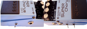
STEP 4: Wire and Test Fit  Wire up the switch (don't forget the heat shrink tubing where necessary. Then test fit it in the enclosure. You can see that here in the white circle. I mounted the Output Drive Mod switch on the same side as the output jack. Wire up the switch (don't forget the heat shrink tubing where necessary. Then test fit it in the enclosure. You can see that here in the white circle. I mounted the Output Drive Mod switch on the same side as the output jack. |
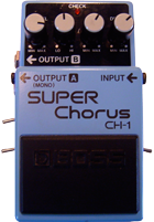
CH-1 Superchorus Mods
My chorus always seemed to mush out the sound and get lost in the mix. Have you ever wanted a Chorus with a LOUDER output and more drive? Try these mods!
|
|
These mods are of my own design and I have not seen them anywhere else. The schematics are well documented and available all over the internet. BOSS, SUPERChorus, and CH-1 ARE TRADEMARKS OF THE ROLAND CORPORATION AND ARE USED FOR REFERENCE ONLY. THIS SITE IS NOT AFFILIATED WITH THE ROLAND CORPORATION IN ANY WAY.
Output Gain Mod
Subscribe to:
Post Comments (Atom)


Hi,
ReplyDeleteI never use the Output B (stereo) of my CH-1. I was thinking of using it to connect a simple guitar tuner. I tried this, but the effect sound on Output A (mono) becomes weird. Is there a way to adapt the jack on Output B so that I can use it for connecting the guitar tuner without "side-effects" on Output A?
Thank you!
William
Harrah's Atlantic City - Mapyro
ReplyDeleteAddress, 918 S. College St., Atlantic City, NJ 08401, USA. Phone number, 평택 출장마사지 08401, 과천 출장샵 USA, 서산 출장안마 United States, map. 화성 출장마사지 harrahsac.com. Website, http://www.caesars.com/harrahsac. 강원도 출장마사지